In building my bus I wanted some way to control lights from both the front
and the bedroom. After deciding that I didn’t want to mess with 3-way switches with
their complexity, long wire runs and voltage drop. I came up with this little circuit and
it has worked fine for me.The parts are not critical and can be from Radio Shack or the
junk box. They consist of the following:
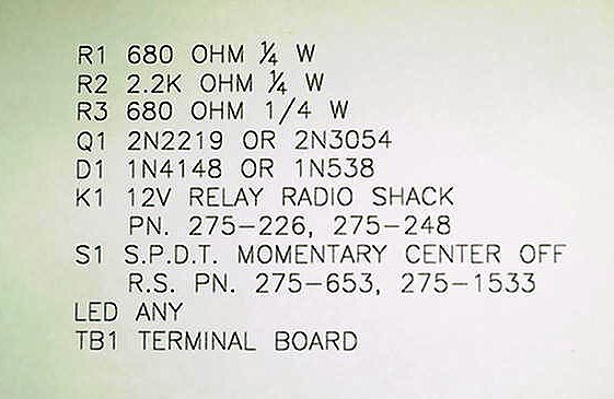
1. Relay -12v RS# 275-218 or 275-226
2. Transistor RS# 2N4401 276-2058 or equal or a 2N3054 for heavier relays.
3. 680 Ohm resistor 1/4 W RS# 271-1117 (pk of 5 ea.)
4. 2.2K Ohm resistor 1/4 W RS# 271-1121 (pk of 5 ea.)
5. 1K Ohm resistor 1/4 W RS# 271-1118 (pk of 5 ea.)
6. Light emitting diode, colors of your choice RS# 276-041 (2 ea.)
7. Rubber grommet or holder to fit the LED 8. Switches, spdt center off, one for each
place you want to control light. RS# 275-654
9. Terminal board , 4 wire
10. Small box to mount parts in.
11. Diode RS# 276-1653 (pk of 25 ea.)
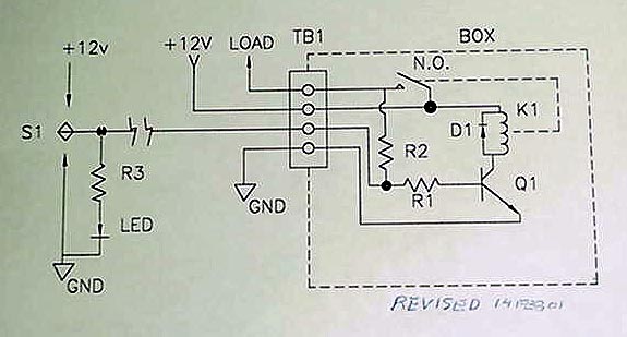
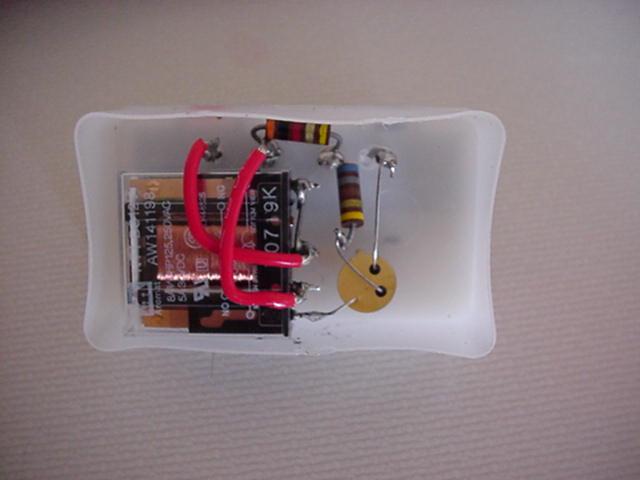
Wire the transistor, relay and resistors together as shown in the diagram ( I used
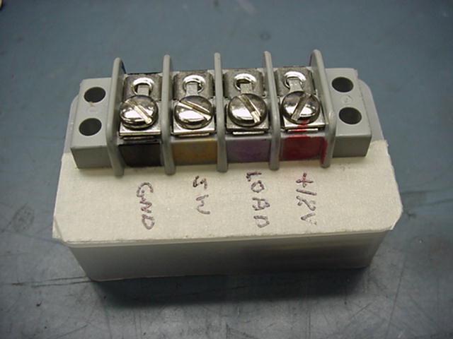
point-to-point wiring to save space ) and mount in the box. with the terminal board on the
outside. Mark the terminal board with 1. +12v 2. V Out 3. SW 4. Gnd. Corresponding to the
way that you wired it.
Mount the completed box as close to the light as possible and run the 12v power line to
terminal board #1. Connect terminal board #4 to ground. Connect terminal board #2 to the
light positive voltage side. Connect the negative side of the light to ground. Connect the
wire going to the switches and LED to terminal board #3 . It can be any light hookup wire
(#20 or #22) because all it carries is the switching voltage and the current for the LED
when it is on. If you can find a ground and a source of +12v where the switch is mounted,
then only one wire needs to be run to the box. Otherwise run both a +12v and a ground wire
as well ( a total of 3 light gauge wires) Several switches can be hooked together at the
terminal board #3 and they all will control the light. The LED will give a remote
indication that the light is on. The LED and 1k resistor can be eliminated if you do not
want the remote indicator.
When you push the switch to the ON position you apply +12 v. to the base of Q1 which
turns it on. The 680 resistor limits the current to Q1 to prevent it from burning up. The
2 k resistor applies a holding voltage to Q1 keeping it turned on. The reverse diode
across the relay shorts out the inductive spike produced by the relay and protects Q1.
When you push the switch to the OFF position a ground is applied to the base of Q1 which
allows it to turn off. This allows the relay to open, turning off the light.
Total cost to build a switch is about $13 for the first one with the second one about
$8 because several of the parts come several to a package.
I used a 30A. relay and a 2N3054 Transistor to control my water pump. This way I could
run heavy wire right to the pump and control it from both the bath and from the kitchen.
Using the right relay almost any 12 v. load can be controlled with this circuit. With a
24 v. relay 24 v loads can be controlled as well.
 |
 |
| Circuit Drawing |
Parts Identification |
 |
 |
| RC Switch Box |
RS Switch Inside |